
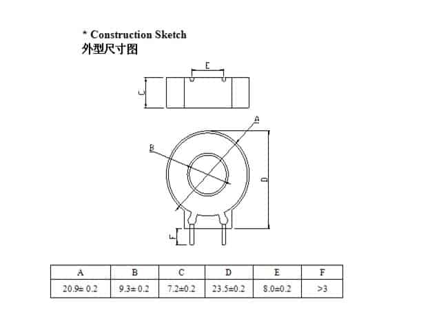
ZCT528 PCB mount zero phase current transformer rated current of transformer
Electrical Specification
(Customized is available)
| Rated Current | 30A |
| DC Resistance at 25℃ | 36±5Ω |
| Dielectric Withstanding Voltage(Hi-pot) | 2500Vrms |
| Output Voltage Vo | 7.5-12mV |
The error is proportional to the average magnetic path length.
The error is inversely proportional to the cross section of the core. In some cases, an increase in the cross section of the core will not only reduce the error, but also increase the error, which wastes material. The length of the core’s magnetic circuit is mainly determined by the area of the core window, and the size of the core window must ensure that the primary and secondary windings can be installed and the insulation between them. After meeting this requirement, the window area of the core should be reduced as much as possible, and the magnetic path length of the core should be shortened. The smaller the magnetic path length of the core, the more provincial the core material, which is obvious at this time. At the same time, the smaller the core’s magnetic path length, the smaller the error, which in turn can reduce the size of the core and save material.
The error is inversely proportional to the cross section of the core.
Generally speaking, increase the core section can reduce errors. However, as the cross section of the core increases, the magnetic permeability of the core decreases.
However, as the cross section of the core increases, the magnetic permeability of the core decreases. As the average magnetic circuit length increases, the internal impedance of the secondary winding increases.
All these greatly limit the reduction of errors small, even in some cases, it also increases the error, which wastes material.
The shape of the core section also affects the error of the transformer. This is because at the same core section, the higher the core, the shorter the average magnetic circuit length. When the core section has the same height and width, the copper wire used for each winding is the shortest. The resistance is also minimal. Therefore, the proportional relationship between the height h and the width b must be correctly selected in the design.
| Item | Rated Current(A) | Output Voltage Vo(mv) | Test Conditions | Over Leakage Characterstics | Temperature Characteristics -35℃~80℃ | Dimensions (mm) |
||
|---|---|---|---|---|---|---|---|---|
| Click PN For Details | ID | OD | HT | |||||
| ZCT501 | 30 | 8-14 | lin=30mA,RL=1kΩ¸ | -10%~0% | 10%Max | 6.8 | 17.3 | 7 |
| ZCT502 | 30 | 6.3-7.3 | lin=22.5mA RL=1kΩ¸ | -10%~0% | 10%Max | 6.8 | 18.2 | 7.2 |
| ZCT503 | 20 | 7.5-10.5 | lin=11.25mA RL=1kΩ¸ | -10%~0% | 10%Max | 5.5 | 15.4 | 6 |
| ZCT505 | 30 | 17-21 | lin=22.5mA RL=1kΩ¸ | -10%~0% | 10%Max | 9.3 | 20.9 | 7.2 |
| ZCT506 | 30 | 17-21 | lin=22.5mA RL=1kΩ¸ | -10%~0% | 10%Max | 5 | 17 | 9.5 |
| ZCT507 | 30 | 25-30.5 | lin=20mA RL=1kΩ¸ | -10%~0% | 10%Max | 6 | 18.6 | 10 |
| ZCT511 | 20 | 4.8-5.1 | lin=20mA RL=1kΩ¸ | -10%~0% | 10%Max | 6.8 | 17.5 | 7.8 |
| ZCT515 | 30 | 3.2-4 | lin=25mA RL=330Ω¸ | -10%~0% | 10%Max | 8.1 | 18 | 6.5 |
| ZCT516 | 40 | 6.3-7.3 | lin=22.5mA RL=1kΩ¸ | -10%~0% | 10%Max | 7.1 | 17 | 19.1 |
| ZCT519 | 50 | 17-22 | lin=11mA,RL=2kΩ¸ | -10%~0% | 10%Max | 9 | 23 | 8.3 |
| ZCT520 | 50 | 20-24 | lin=20mA RL=1kΩ¸ | -10%~0% | 10%Max | 12 | 26.7 | 11 |
| ZCT526 | 40 | 25-30 | lin=25mA RL=1kΩ¸ | -10%~0% | 10%Max | 5.8 | 19.3 | 7.8 |
| ZCT528 | 30 | 7.5-12 | lin=30mA,RL=1kΩ¸ | -10%~0% | 10%Max | 9.3 | 20.9 | 7.5 |
| ZCT534 | 40 | 6.4-7.5 | lin=20mA RL=1kΩ¸ | -10%~0% | 10%Max | 6.8 | 17.4 | 6.5 |
| ZCT538 | 30 | 3.6-3.8 | lin=500mA,RL=150Ω¸ | -10%~0% | 10%Max | 5.5 | 15.4 | 5.3 |
| ZCT541 | 50 | 12-13 | lin=25mA RL=330Ω¸ | -10%~0% | 10%Max | 9 | 22 | 8.3 |
| ZCT543 | 20 | 3.5-4.5 | lin=20mA,RL=370Ω¸ | -10%~0% | 10%Max | - | - | 6.4 |
| ZCT547 | 30 | 15-18 | lin=500mA,RL=150Ω¸ | -10%~0% | 10%Max | - | - | 17 |
| ZCT548 | 30 | 13.2-17.8 | lin=11mA,RL=360Ω¸ | -10%~0% | 10%Max | 19 | 5 | 7.5 |